 |
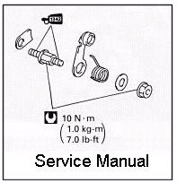
Here is the Service Manual diagram for the
Stopper Comp assembly. There are two things worth noting
here. First is that the torque specs for the Stopper
Comp assembly which is listed as 7.0 lb-ft. The second
thing to note is that the service manual is wrong.
This diagram shows the Stopper Comp arm as being between the spring and the shoulder to the rear of the assembly stud. When I took my bike apart I found that the Stopper Comp arm was behind the shoulder directly in front of the rear spacer. My bike was put together wrong... or that's what I thought at first. |
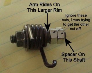 |
Here is what the Stopper Comp
assembly looks like when you try to take the front nut
off and rather than that happening the entire assembly (stud) comes out
(I'll get to why that happened in a minute). Ignore the two silver nuts on that stud, I put those on there trying to get the front nut off so I could replace the spring so don't pay any attention to that, but take a look at the raised shoulder between those nuts and the spring. That shoulder is what the Stopper Comp arm rides on and then a spacer goes behind it. |
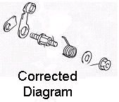 |
After looking at
that, I came to the
conclusion that my bike was put together right, but that
the service manual is incorrect. The diagram at left
shows how the service manual should show this assembly.
Under the spring there is a large 'hex' type shape built onto that stud, it is large enough that the Stopper Comp arm will not fit over it as indicated in the service manual. The way my bike was assembled, as reflected in the corrected version at left, is the only way that it can go. Okay, so the service manual is wrong. |