| Download this site as .PDF file (right click and save as) |
| Download the .DOC file (right click and save as) provided by Luke - Coolhand |
| HD Switch - provided by Rasoul - Aryajet |
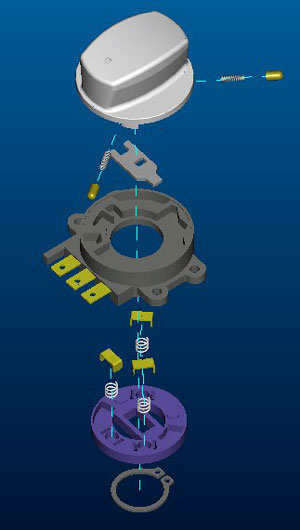
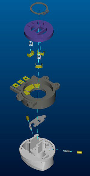
| Here are 2
exploded view of HD switch. Some people put them self in trouble during the reassembly of the switch, these pix will help you out. |
 |
| I’ve got
all the pictures ready for you and hope I could wrap it up tonight. It
will be around 10 posts so please don’t reply to it until we get to
the end of it When you start doing the work you need to have Mocc’s
web-site opened at the same time, he saved most of the Tools, electrical
and other parts information in there when I posted them for the first
time.
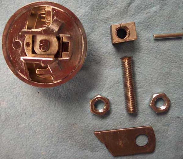
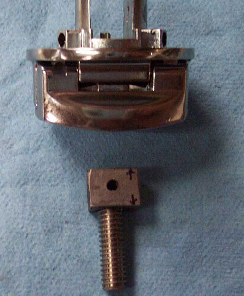
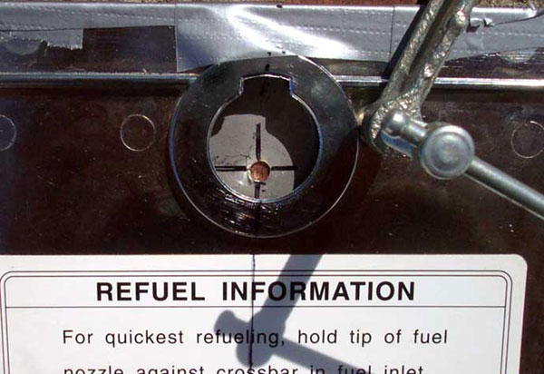
First picture will show you the famous Aluminum Block, this block could be any kind of metal (the softer the better) Steel, Brass, copper Bronze or even hard composite material like PVC (I think Larry JHawk called it Aluminum and the name got stock). Block needs to be 9/16 inch long, 5/16 wide and 3/8 high. None of these numbers are etched in Stone, obviously they can’t be larger but if you have something smaller it will be OK, length and height are not critical but if you have something narrower you can fill up the gap with plastic shims or even Duct-tape, I guess that is why they call it Custom made. In this pic. You see the parts required for Fuel Door Locking mechanism. The Block, 2 Jam nuts, Stud (which it actually 5/16-18 SS Bolt with shank and head sawed of), locking latch and the rolled pin. Stud and Jam Nuts are all 5/16-18 but you can use any size from 1/4 inch all the way up to 3/8. I picked that size since it is the most common fastener size in hard ware stores. BTW I don’t know why they look like Copper in the picture but they are all Stainless steel. |
 |
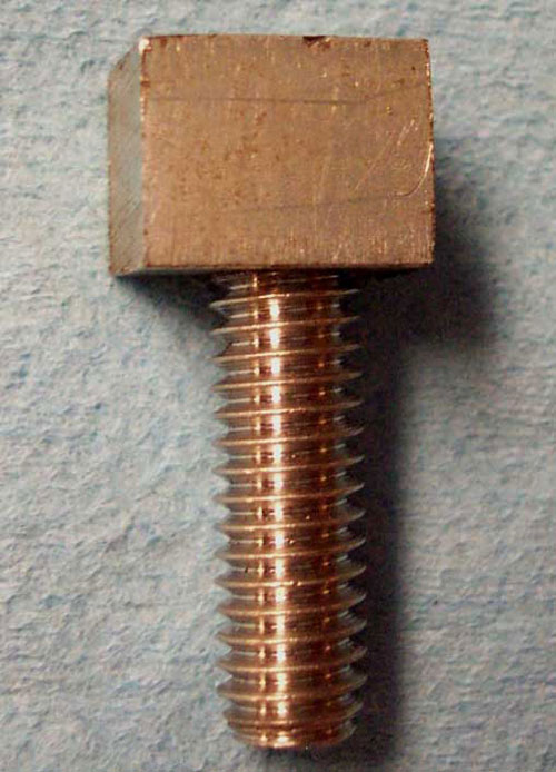
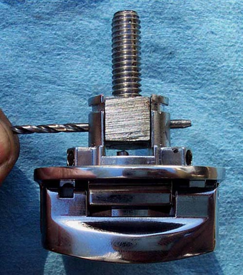
| Ok, that 5/16-18 stud will require 9/32 drill bid but I would start with smaller pilot hole and go up may be in 3 steps. When I was installing the stud in the block I used some Red Lock-Tite not to secure it in there but to stop it from rotating while drilling for the Rolled pin. After you insert the Rolled pin in that baby is not turning under any circumstances. Now you see a Bolt that resembles letter T which its head will rest between the EARS on the HD Switch housing. Here is the Pic. |
 |
| This one will show you the hole for the rolled pin. You insert the Block in the center of the switch housing and drill the hole through all 3 parts at the same time. I removed it after drilling for the Photo only. |
 |
| Drill
bid size for the Rolled pin depends on what diameter pin you are using,
what ever that measurment is, pick a bid 1/32 smaller. This picture
will show you where the pin will be installed (drill bid is for
demostration). IMPORTANT.....remeber to install Locking Latch and Spring(you will exactley know which Latch and spring I'm talking about when you disassemble your HD switch) under the Block and Stud before inserting the Pin. |
 |
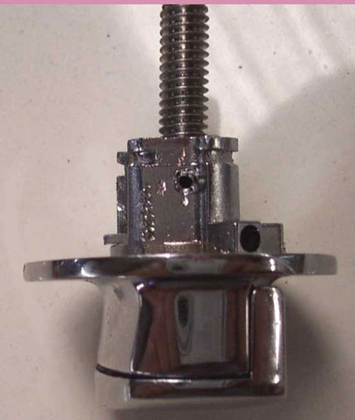
| Ok here it is. You have installed the Locking latch and Spring then reseted the block&Stud between Switch's Tabs, then lined up the holes and drive Rolled pin Through. Grind and smoothen both end of the Pin flush with Housing's sides. Now you are ready to set this baby aside. |
 |
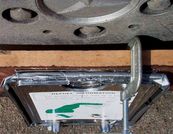
| Time for drilling the BIG hole. This picture shows you some very important elements. You see I'm using a Hard Wood backing plate to have my Hole Saw's Pilot Bit to rest on, since I don't trust wood as a solid base I sandwiched a thin sheet metal between the Fuel Door and Wood then clamped all 3 together. |
 |
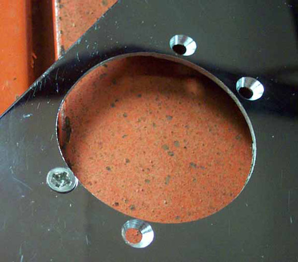
| I used 1 and 3/4 of an inch Hole saw to do this which is tad smaller than new Switch's OD. Then I used 1 and 3/4 inch Drum Sander Bid chucked on a hand held Drill, then fine tuned this hole till Switch housing just passed through. Randy the Bushwhacker says he used 1 and 7/8 inch hole saw and result was perfect you might try that as I said dimensions are not that critical. You see here that center of the big hole doesn't match with the center of the Stock fuel door opening, well IMAGINE how did I figure that out....LOL. your Center Punch should rest 1/4 of the diameter above 6 O'clock position of the existing hole, OK you don't think That I'm clear at all, you are right this why I'm getting help from pictures. (again this 1/4 thing is NOT critical). Put the dent right there and drill your small pilot hole. |
 |
| Scary
part is done, what you see in back ground through the big hole is the
Thin Sheet Metal backing plate which at this point it has superseded its
usefulness. Btw You noticed up to this point the Black Beauty Sticker on the top side the fuel door was not disturbed so it has the same hole as the fuel doors metal portion. |
 |
| Trial
fit of the Switch Housing through the new opening. Please note the
entire top surface of the Fuel Door is covered with Duct tape......Ha Ha
Ha we all like Chrome and praise that vocabulary but at the same time we
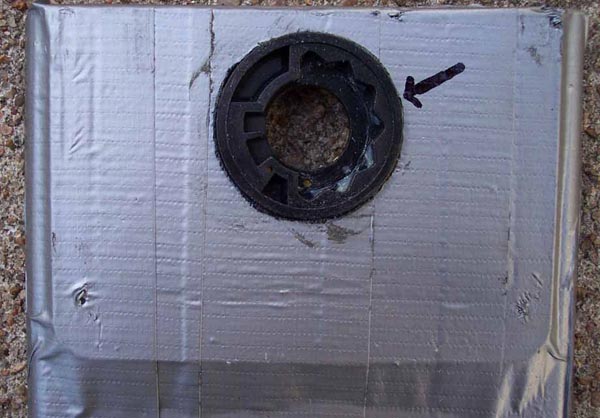
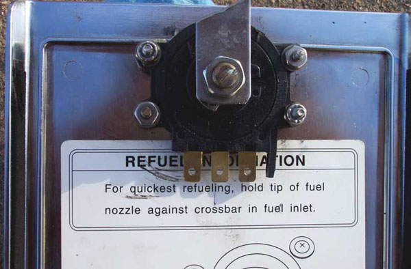
believe SCRATCH is Evil. Please take a note of the Arrow, during final Assembly you might want to apply a dab of black RTV all the way around this spot just to make yourself feel proud, Since Fuel filling compartment was designed to be Water tight when Bike left Japan. |
 |
| Now at this point proceed with peeling off the Black Sticker. I'm sure you will come up with better solution than mine. I don't how many of these thing I have done and so far I know of only one Chemical that will make removing and cleaning of the residue related to this sticker and that is PATIENCE. Just get a wooden spatula, peel it off then use Patience and your finger tips to remove Kamikaze Double-sided Tape. Put Center Switch housing back in the opening, using the 4 mounting Ears as guides mark and drill 6-32 holes for the screws. Flip over the Fuel Door and counter sink holes as you see in this picture. |
 |
| In this picture you see the type of plastic spacers I used to adjust mounting height of the Switch's center housing. Basically the concept is....when you are done installing and tightening all 4 screws, top of the housing should be flush with top surface of the Black Sticker ( refer to picture with Duct Tape and Arrow). 98 and 99 LCs have paper thin stickers, late models have thick plastic ones. For the Thick plastics I used 3/16 inch Spacers. I put some extra Spacers for photo and these guys are available from any hard ware store in several different sizes. |
| Install center housing, tighten the screws, stick the Black Sticker back on..... nothing will work better than Double sided tape here. During assembly of Switch components use small amount of heavy wheel bearing grease on Tabs and Springs this will retain those Small parts during final assembly also it is good for their proper operation and longevity. After you are done with the Switch, screw in the bottom Jam-Nut then the Home made Fuel Door latch and finally the top Jam-Nut. At this point the entire Gizmo is ready to be installed on the Bike for final adjustment. Ooh ya there is a small process of final adjustment |
 |
 |
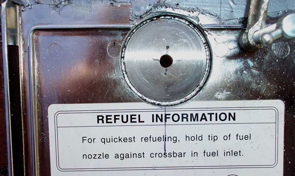
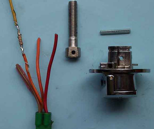
| The following picture will show you how the right location of the resistor. |
 |